Heya folks,
Few days ago I received my some of the tools for my electronic projects (such as: oscilloscope, Arduino and Multimeter). We (William and I), configured an Arduino to test the oscilloscope by creating a simple square waves. Based on today’s experiment, we accomplished/discovered two interesting things:
- Near perfect square wave with no phase shift (117kHz frequency).
We tested to see the frequency for 50% (no scale) by using analogWrite() function (reference).
For this configuration, we noticed no phase shift on the analog side of the equation. However, after we tested with digitalWrite() (see reference), we noticed 1/4 of phase shift on our square wave (will update with image later).
To solve this clock slips/phase shift problem, we did a little research and concluded that one of the reasons of the shift problem is due to interruption on the main (Arduino) code. Hence, we modified the code by adding noInterrupts() (see: reference).
//The commented code were used to test elimination of phase
// shift before using the noInterrupts() function
//unsigned int usdelay =1;
void setup() {
  noInterrupts();
  pinMode(3,OUTPUT);
  pinMode(4,OUTPUT);
  digitalWrite(3, LOW);
  digitalWrite(4, LOW);
}

void loop() {
  // put your main code here, to run repeatedly:
  digitalWrite(3, HIGH);
  digitalWrite(4, HIGH);
  //delayMicroseconds(usdelay);
  digitalWrite(3, LOW);
  digitalWrite(4, LOW);
  //delayMicroseconds(usdelay);
}
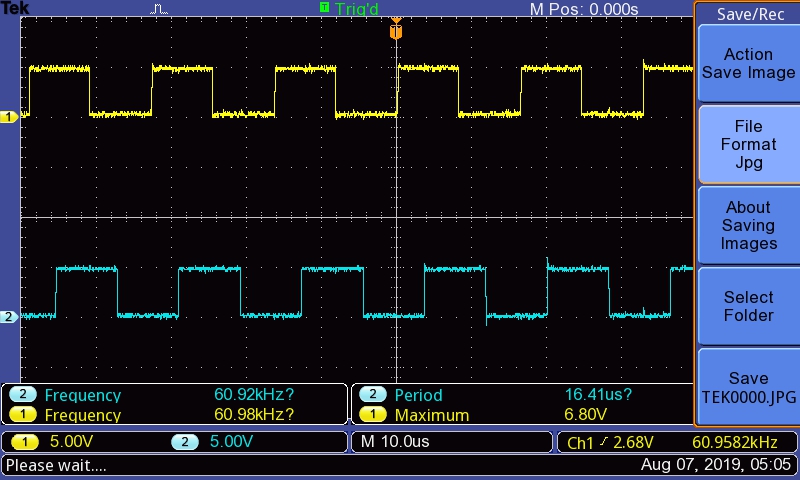
For amplitude 5V, we managed to produce desired frequency: 117kHz (1 pin as INPUT) or 60.9kHz (for two pins as INPUT) without phase shift with the noInterrupts() solution.
2. Cross-talk problem using serial connection
We tested the serial connection with 9600bps and using 0xAA (Binary: 1010 1010 <– you can also imagine this as LOW, HIGH, LOW, HIGH,…, HIGH) pattern, and somehow our configuration introduced a cross-talk problem from the pin#4 we set-up as input (!!!).
void setup() {
  Serial.begin(9600);
  pinMode(4, INPUT);
  digitalWrite(4, LOW);// pin#4 LOW means High Z
  }

void loop() {
  Serial.write(0xAA);
}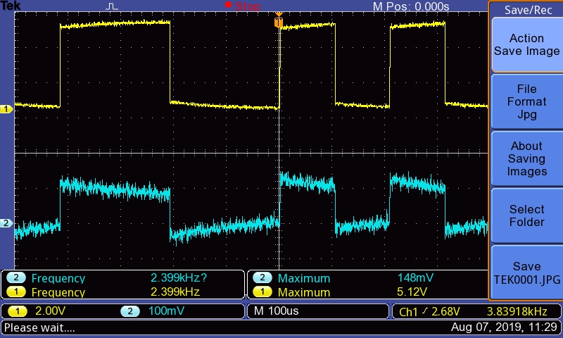
As we can see from Figure 2, channel 2 (blue) is the square wave from pin#4 and channel 1 (yellow) is the square wave from the serial connection (tx) from the Arduino. We noted that the amplitude of the pin#4 is very low (148mV) compared to the amplitude of channel 1 (5.12V).
That’s all for today. Will test 2 Arduinos later.
Peace, Love, Mango

Leave a comment