Heya folks,
Happy weekend to all of you! We had heavy rain on Saturday morning, and it was nice and good for my plants.
We did a simple linear test with Arduino by using the Tx pin (USART) and to test the highest baud rate it can handle before it introduce some weird stuff on oscilloscope.
//Again, pin#4 being LOW means for HIGH Z
//the baud rate in this code is the highest rate that we tested and it had some nasty wave on oscilloscope
void setup() {
  Serial.begin(2500000);
  pinMode(4, INPUT);
  digitalWrite(4, LOW);
}
void loop() {
   Serial.write(0xAA);
}| Baud Rate(Bps) | Period ( μs) | Frequency(Hz) |
| 9600 | ~104.2 | 9596 |
| 19200 | ~52.07 | 19204 |
| 38400 | ~26.04 | 38402 |
| 76800 | ~13.02 | 76804 |
| 153600 | ~6.512 | 153562 |
| 230400 | ~4.509 | 221778 |
| 460800 | ~2.004 | 499001 |
| 921600 | ~1.002 | 998003 |
| 1843200 | ~0.5012 | 1995000 |
| 2000000 | ~0.5011 | 1995609 |
| 2500000 | ~0.5014 | 1995609 |
Based on data above, we noticed that although it maintain the linear behavior, the higher the baud rate (the corresponds frequency value should be very close to the baud rate), the higher the deviation of the frequency rate.
Check out the screenshots from two different baud rate:
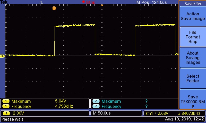
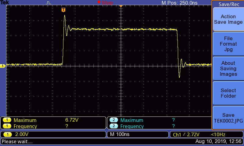
Just by eyeballing those two screenshots, we know that at period 250nanoseconds, the square wave behave abnormally (it has some negative peak, which we don’t want).
We could say that it is feasible to transmit 1Mbs, BUT definitely less than 2.5Mbs!
Tomorrow we will use two Arduino to test both Tx and Rx modules. That’s all for now, enjoy the rest of your weekend.
Also, check out Thom Yorke’s new album:
Cheers,

Leave a comment