Heya,
Unfortunately I am back to school again, but I only have one hard class (designing op amp), and 2 garbage classes, so I probably will continue working on this.
Last time, I managed to transmit signals over 1000 foot UTP cable. However, to check whether it was garbage signals or not we need to generate eye-diagram to analyze our signals. I had no luck creating appropriate eye-diagram due to the code I uploaded to the Arduino. I needed something that have separate clock and something random.
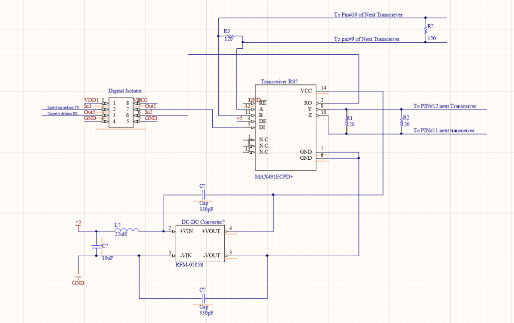
Talking about random, I thought about linear–feedback shift register (LFSR). LFSR is a shift register and with a feedback of two or more “taps”. Based on the circuit schematic shown in Picture 1, I tapped bit 0 and 2. You can of course tap more than two, however, there are certain of pattern you need to follow (refer to Picture 2) that can be referred to the length of the loop.


Moreover, LFSR would spit out pseudo-random numbers that I need for my eye-diagram testing. The previous set up with Arduino was bad because it spit out constant pattern that of course you can’t analyze whether your signal is bad or not.
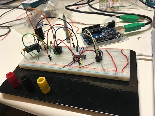
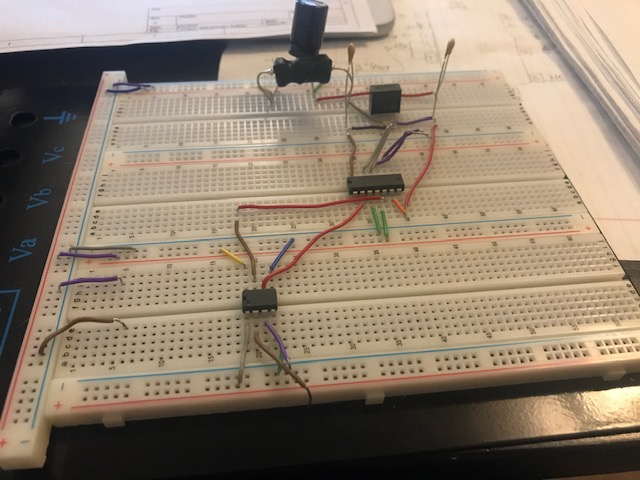
So, I built LFSR with d-flip flop (using TI SN74LS273N), and XOR gate ( HD74LS86 )

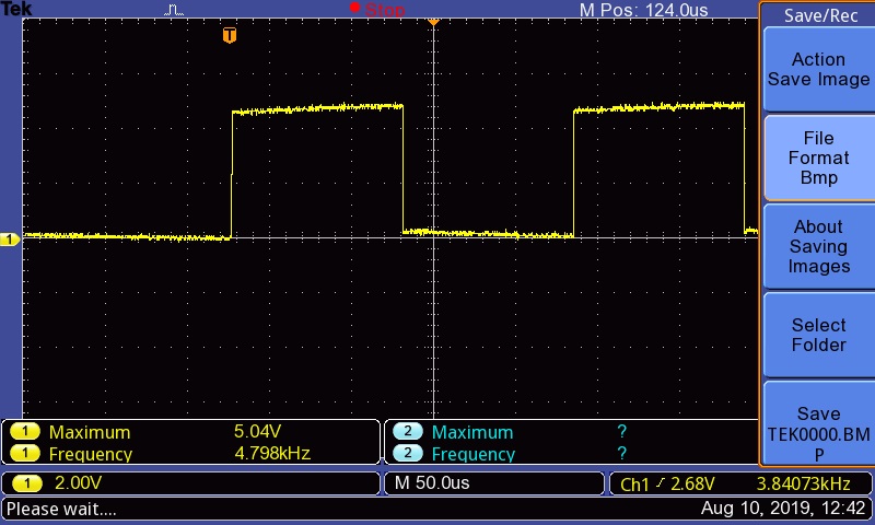
Using the circuit set up from Picture 1 (a), I use function generator as a clock for the D-flip flop, and output it from pin #6 of the d-flip flop (since I’m only using 2 taps).
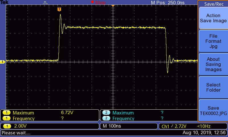
anddddd there she is, the not so pretty eye-diagram (lol). But it’s a progress!