Hello people!
It’s been a while since my last post. I actually did a little summer activities (hiking, gardening, rearranging pantry, making soap etc). BUT I also managed to design the circuit schematic for my serial communication project.
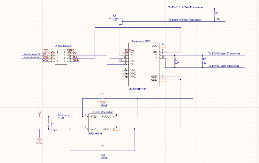
The schematic as shown in Figure 1 is very drafty. I was using Altium Designer for it, but since I am not making PCB at this moment, I thought this should be doable as my breadboarding reference. Again, this schematic is awful because you can’t really see the flow from the original to the isolation section. I will fix it later!
Breadboarding part I: Look at those loops!
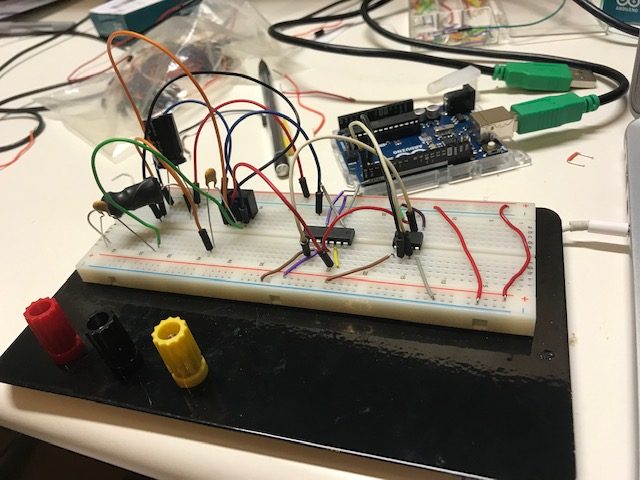
Then I realized that those loops could introduce unwanted inductance, so I revised.
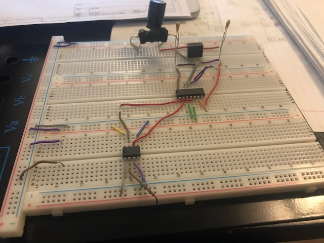
As you can see, they look so much better! FLAT. You’d want them flat like that. It’s a tedious work, but I shall get used to it.
For multigiga serial links (with increasing bitrates), it would suffer from signal distortions. While SerDes receiver designed to compensate those distortions, by creating a bigger eye opening (see: eye diagram) for reliable sampling, the bit rates also rising faster than Rx, PCB, and package HDI. This results in decreasing reachable total channel. RS-485 is a type of repeater that could restore the signals, hence RS-485 extending the channel reach.
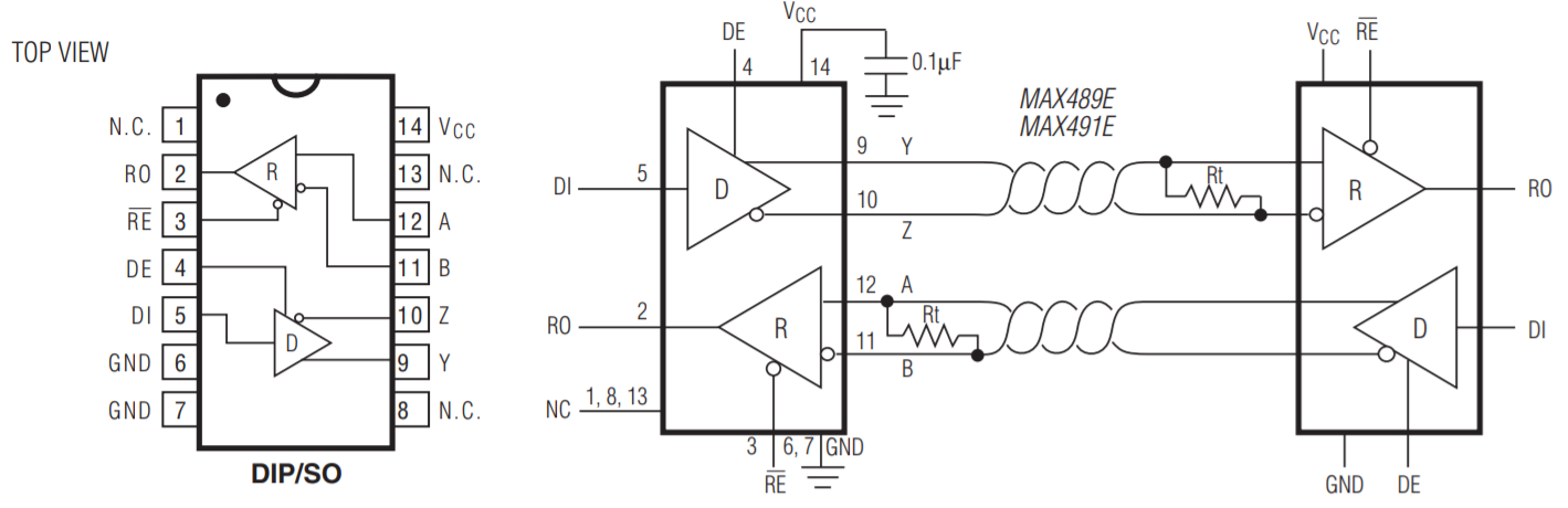
RS-485 use differential signaling over twisted pair, which is beneficial. We know from circuit theory, that differential signaling technique reduces electromagnetic interference (EMI) that could cause cross-talk. In addition, RS-485 also use 3-state logic (1, 0 and high Z) that allows individual transmitter to be deactivated.
The schematic and circuit board above (see Figures 1,2,3), uses RS-485 as a repeater and it connected it to digital isolator to ensure the power-supply voltage to the MCU is compatible and DC-DC converter to rectify the whole process back to the DC.
If you notice, the circuit diagram for DC-DC converter contains Inductor(L) and Capacitor (C). The LC circuit is a simple low pass filter to filter out unwanted signals that may present above the wanted pass band.
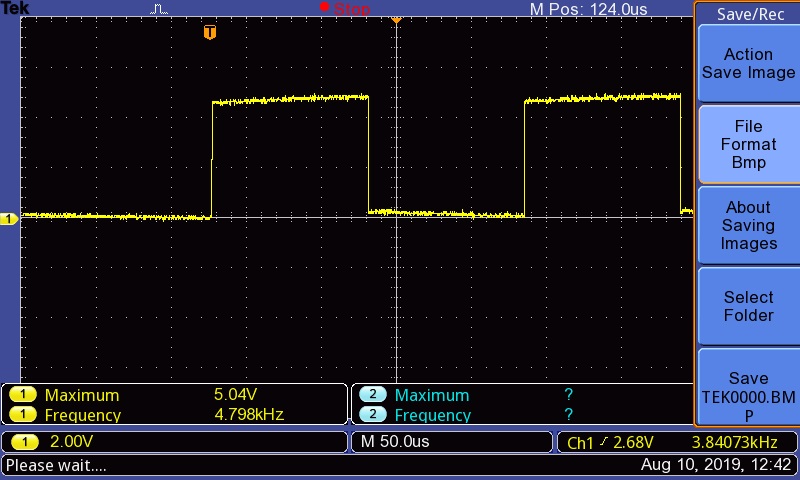
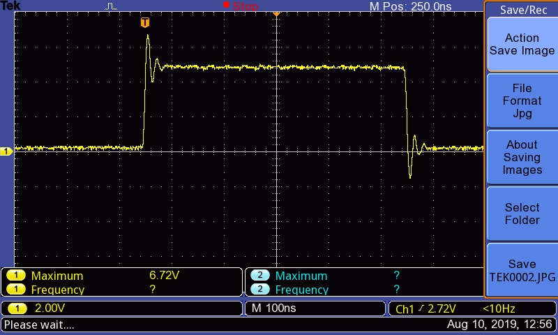
So in theory, once we connect all of these out to the UTP cable, 50m cable should not signal faster than 2Mbit/s. We’ll see!
Will keep you updated.
Source: https://www.intel.com/content/www/us/en/io/serial-bus-white-paper.html